Let's construct a simulation model of a crank-slider mechanism, an important machine element. This simulation model includes several new joints: "clamp," "in-line," "prismatic," and "axial rotation." A "drive caller," which can provide a time-dependent input, and a "force" element also appear in this model.
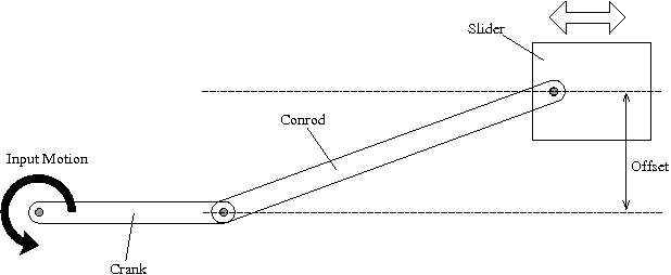
Construct a simulation model of a crank-slider mechanism as shown in Figure 1. Let the lengths of the crank and the conrod, the offset of the slider, and the masses of all parts be the design variables and create an input file that allows the user to conduct simulations while freely changing the values of those design variables.
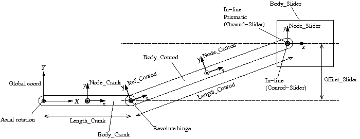
A plan of the simulation model of the crank-slider mechanism for Problem 5 is shown in Figure 2. Let the center of rotation of the crank be the origin of the global reference frame and construct the model in the plane of Z=0 in an arrangement shown in the figure. The nodes for the crank and the conrod are placed at each center of mass. We define a reference "Ref_Conrod" at the connection point of the crank and the conrod as shown in the figure, which is convenient to succinctly define the node of the conrod "Node_Conrod" and the connection point of the conrod and the slider.
This model uses the following four new joint elements.
Among them, "clamp," "in line," and "prismatic" joints are described in the following. "Axial rotation" is treated in the next chapter.
This joint constrains all six degrees of freedom of a node and fixes the node to the global frame in an arbitrary position and orientation. The basic syntax for the statement that defines a clamp joint is as follows.
   joint: <label>,
      clamp,
         <node>,
            <absolute position>,
            <absolute orientation matrix>;
This joint constrains a node on a straight line fixed to another node. The basic syntax for the statement that defines an in-line joint is as follows.
   joint: <label>,
      in line,
         <node 1>,
            <relative line position>,
            <relative orientation>,
         <node 2>,
            [ offset, <relative offset> ];
<node 2> (or the point offset by <relative offset>) is constrained on the straight line fixed to <node 1> that goes through <relative line position> and is parallel to the z-direction defined by <relative orientation>.
This joint constrains the relative orientation of two nodes. In effect, one node moves while keeping its orientation relative to the other node. The relative position is not constrained. The basic syntax for the statement that defines a prismatic joint is as follows.
   joint: <label>,
      prismatic,
         <node 1>,
            [ hinge, <relative orientation matrix 1> ],
         <node 2>,
            [ hinge, <relative orientation matrix 2> ];
The initial orientation of the joint can be defined by "hinge." The orientations of the two hinges have to be consistent.
For our simulation model of a crank-slider mechanism, we constrain the slider so that it can move on a straight line parallel to the global X-axis while keeping its orientation unchanged. This can be achieved by constraining the slider with respect to the global frame with a prismatic joint and an in-line joint.
First, since we need a node that is fixed to the global frame, we create it. We define a static structural node "Node_Ground" at the origin and fix it to the global frame with a clamp joint.
set: integer Node_Ground = 1;

structural: Node_Ground, static,
   0., 0., 0., # absolute position
   eye,        # absolute orientation
   null,       # absolute velocity
   null;       # absolute angular velocity
set: integer JoClamp_Ground = 1;

joint: JoClamp_Ground,
   clamp,
      Node_Ground,
         null, # absolute position
         eye;  # absolute orientation
Next, we constrain "Node_Slider" on a straight line with an in-line joint and its orientation with a prismatic joint with respect to "Node_Ground."
set: integer JoInlin_Ground_Slider = 5;
set: integer JoPrism_Ground_Slider = 6;

joint: JoInlin_Ground_Slider,
   in line,
      Node_Ground,
         0., Offset_Slider, 0.,         # relative line position
         1, 0., 0., -1., 3, 1., 0., 0., # relative orientation
      Node_Slider;

joint: JoPrism_Ground_Slider,
   prismatic,
      Node_Ground,
      Node_Slider;
The constraints on the crank and the conrod are almost same as those on the links of the double rigid pendulum in Chapter 14. The only difference is that instead of a "revolute pin" an "axial rotation" is used in this case. Axial rotation is a joint that, in addition to the constraint equivalent to a revolute hinge, can impose arbitrary angular velocity. Axial rotation is described in the next chapter.
How should we connect the conrod and the slider? It seems from the structure that we should connect them with a revolute hinge. But we cannot connect them with a revolute hinge because if we do so, the model becomes over-constrained. A model becomes over-constrained when we try to constrain a degree of freedom that is already constrained. In our case, since both the conrod and the slider are already constrained in the Z-plane, if we try to further constrain the two to be in a same plane with a revolute hinge, they become over-constrained. MBDyn cannot address an over-constrained model. To connect the conrod and the slider without making them over-constrained we use an in-line joint. At the connection point we constrain "Node_Slider" on a straight line that is fixed to the conrod and parallel to the Z-axis.
set: integer JoInlin_Conrod_Slider = 4;

joint: JoInlin_Conrod_Slider,
   in line,
      Node_Conrod,
         Length_Conrod/2., 0., 0., # relative line position
         eye,                      # relative orientation
      Node_Slider;