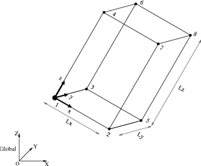
A block shape in a general configuration as shown in Figure 1 can be defined by the position and the orientation of the reference frame attached to one of the vertices and the length of each side (Lx, Ly, Lz). If the position coordinate and the orientation matrix of the reference frame are r and R, respectively, then the coordinates of the vertices are obtained by the following equation:
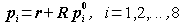
where p0i is the coordinate of the i-th vertex in the basic configuration. If the coordinates of the vertices are obtained, we can make the block shape by combining six polygons using plot3d command in the same way as in the last section.
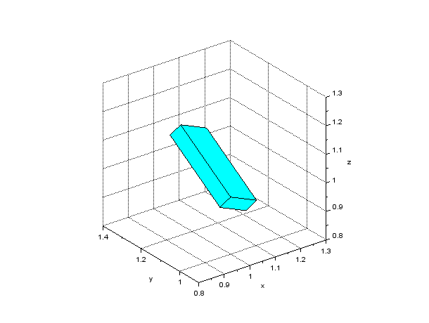
A Scilab script to draw a block shape in a general configuration is shown in Code 1. The result of the drawing by this script is shown in Figure 2. Function eulerXYZ() used in the script is a function that converts XYZ Euler angles to the corresponding rotation matrix and is defined as in Code 2. Also, transver() is a function that transforms a vertices matrix according to the coordinate transformation formula shown above and is defined as in Code 3.
// make_block_general.sce

clear; xdel(winsid());

exec('eulerXYZ.sci', -1);
exec('transver.sci', -1);
exec('genpat.sci', -1);

// Reference position
r = [1; 1; 1];

// Reference orientation
R = eulerXYZ(-%pi/3, 0, %pi/6);

// Side lengths
Lx = 0.15;
Ly = 0.05;
Lz = 0.30;

// Vertices
vertices_0 = [
    0,   0,  0;  // #1
    Lx,  0,  0;  // #2
    0,  Ly,  0;  // #3
    0,   0, Lz;  // #4
    Lx, Ly,  0;  // #5
    0,  Ly, Lz;  // #6
    Lx,  0, Lz;  // #7
    Lx, Ly, Lz]; // #8

vertices = transver(vertices_0, r, R);

// Faces
faces = [
    1, 2, 5, 3;  // #1
    1, 3, 6, 4;  // #2
    1, 4, 7, 2;  // #3
    4, 7, 8, 6;  // #4
    2, 5, 8, 7;  // #5
    3, 6, 8, 5]; // #6

// Patches
patches = genpat(vertices, faces);

// Draw patches
h_fig = figure;
h_fig.background = 8;
h_pat = plot3d(patches.x, patches.y, patches.z);
h_pat.color_mode = 4;
h_pat.foreground = 1;
h_pat.hiddencolor = 4;

// Axes settings
xlabel("x"); ylabel("y"); zlabel("z");
h_axes = gca();
h_axes.isoview = "on";
h_axes.box = "off";
h_axes.rotation_angles = [63.5, -127];
h_axes.data_bounds = [0.8, 0.9, 0.8; 1.3, 1.4, 1.3];
xgrid;
function R = eulerXYZ(a1, a2, a3)
// Convert XYZ Euler angles to rotation matrix

R1 = [
    1, 0, 0;
    0, cos(a1), -sin(a1);
    0, sin(a1), cos(a1)];

R2 = [
    cos(a2), 0, sin(a2);
    0, 1, 0;
    -sin(a2), 0, cos(a2)];

R3 = [
    cos(a3), -sin(a3), 0;
    sin(a3), cos(a3), 0;
    0, 0, 1];

R = R1*R2*R3;

endfunction
function vertices = transver(vertices_0, r, R)
// Transform vertices by translation vector r and rotation matrix R

vertices = repmat(r', size(vertices_0, 1), 1) + vertices_0*R';

endfunction