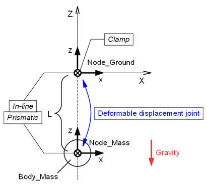
本項では、structural internal forceの代わりに“deformable displacement joint”を用いてバネとダンパーを表現し、前項で作成したバネ‐マス‐ダンパー系のシミュレーションモデルと同等なモデルを作成します。
ジョイントは通常、ハードな拘束条件を付加して系の自由度を減らしますが、次の3つの“deformable”ジョイントは例外です。
これらのジョイントは“deformble”の名の通り、2つのnodeを弾性力や粘性力で結びつけます。“ゴムの塊”のようなもので2つの剛体を接続することをイメージすると良いでしょう。diformable displacement jointは並進方向のみ、deformable hingeは回転方向のみ、そしてdeformable jointは並進方向と回転方向の両方に弾性力や粘性力を働かせることができます。弾性力や粘性力の特性は“constitutive law”によって定義します。constitutive lawはとても多くの種類がありますので、詳しくは公式のInput manualを参照してください。
このジョイントは、2つのnode(またはオフセットした点)の間に並進方向の弾性力や粘性力を働かせます。deformable displacement jointを定義する基本的なステートメントの型は次のようになります。
   joint: <label>
      deformable displacement joint,
         <node 1>,
            <relative offset 1>,
          [ hinge, <relative orientation matrix 1>, ]
         <node 2>,
            <relative offset 2>,
          [ hinge, <relative orientation matrix 2>, ]
         <constitutive law>;
<constitutive law>はnode1の座標系を参照します。
一般に、deformable displacement jointを用いてバネとダンパーを表現することができます。本例題の場合、次のようにdeformable displacement jointを定義します。(図1参照)
   set: integer JoDfmd_SpringDamper = 4;

   joint: JoDfmd_SpringDamper,
      deformable displacement joint,
         Node_Ground,
            null, # relative offset
         Node_Mass,
            null, # relative offset
         linear viscoelastic isotropic,
            K,    # stiffness
            C,    # viscosity coefficient
         prestrain, single, 0., 0., -1, const, L;
ここで、バネとダンパーは線形なので、constitutive lawは“linear viscoelastic isotropic”を使用します。また、バネは自然長 L > 0 を持つので、“prestrain”でこれを定義します。
deformable displacement jointを用いてバネとダンパーを表現した場合の、例題8のバネ‐マス‐ダンパー系の入力ファイルを以下のコード1に示します。
# spring_mass_damper_2.mbd

#-----------------------------------------------------------------------------
# [Data Block]

begin: data;
   problem: initial value;
end: data;

#-----------------------------------------------------------------------------
# [<Problem> Block]

begin: initial value;
   initial time:   0.;
   final time:     5.;
   time step:      1.e-3;
   max iterations: 10;
   tolerance:      1.e-6;
end: initial value;

#-----------------------------------------------------------------------------
# [Control Data Block]

begin: control data;
   skip initial joint assembly;
   output frequency: 10;
   structural nodes: 2;
   rigid bodies:     1;
   joints:           4;
   gravity;
end: control data;

#-----------------------------------------------------------------------------
# Design Variables
set: real M = 1.;  #[kg] Mass
set: real L = 1.;  #[m] Spring Natural Length
set: real K = 20.; #[N/m] Spring Stiffness Coefficient
set: real C = 1;   #[Ns/m] Damper Damping Coefficient

#-----------------------------------------------------------------------------
# Node Labels
set: integer Node_Ground = 1;
set: integer Node_Mass   = 2;

# Body Labels
set: integer Body_Mass = 1;

# Joint Labels
set: integer JoClamp_Ground      = 1;
set: integer JoInLin_Ground_Mass = 2;
set: integer JoPrism_Ground_Mass = 3;
set: integer JoDfmd_SpringDamper = 4;

#-----------------------------------------------------------------------------
# [Nodes Block]

begin: nodes;

   #-----------------------------------------------------------------------------
   # Nodes
   structural: Node_Ground, static,
      null, # absolute position
      eye,  # absolute orientation
      null, # absolute velocity
      null; # absolute angular velocity

   structural: Node_Mass, dynamic,
      0., 0., -L, # absolute position
      eye,        # absolute orientation
      null,       # absolute velocity
      null;       # absolute angular velocity

end: nodes;

#-----------------------------------------------------------------------------
# [Elements Block]

begin: elements;

   #-----------------------------------------------------------------------------
   # Bodies
   body: Body_Mass, Node_Mass,
      M,    # mass
      null, # relative center of mass
      eye;  # inertia matrix

   #-----------------------------------------------------------------------------
   # Joints
   joint: JoClamp_Ground,
      clamp,
         Node_Ground,
            null, # absolute position
            eye;  # absolute orientation

   joint: JoInLin_Ground_Mass,
      in line,
         Node_Ground,
            null, # relative line position
            eye,  # relative line orientation
         Node_Mass;

   joint: JoPrism_Ground_Mass,
      prismatic,
         Node_Ground,
         Node_Mass;

   joint: JoDfmd_SpringDamper,
      deformable displacement joint,
         Node_Ground,
            null, # relative offset
         Node_Mass,
            null, # relative offset
         linear viscoelastic isotropic,
            K,    # stiffness
            C,    # viscosity coefficient
         prestrain, single, 0., 0., -1, const, L;

   #-----------------------------------------------------------------------------
   # Gravity
   gravity: 0., 0., -1., const, 9.81;

end: elements;
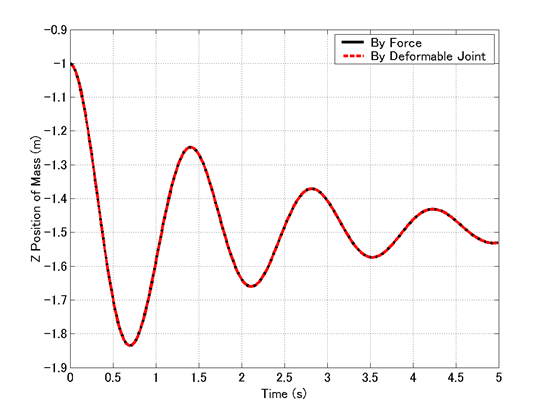
図2は、structural internal forceとdeformable displacement jointのそれぞれを用いて作成した、2つのバネ‐マス‐ダンパー系シミュレーションモデルのシミュレーション結果の比較です。これより、2つのモデルが全く同等であることが確認できます。