1自由度のバネ‐マス‐ダンパー系のシミュレーションモデルを作成してみましょう。ここでは、バネとダンパー(減衰器)を表現する2つの方法を紹介します。まず本項で、“structural internal force”を“plugin variable”とともに用いる方法を紹介します。そして次項で、“deformable displacement joint”を用いる方法を紹介します。
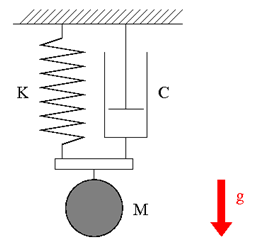
図1のように、天井から吊り下げられたバネ‐マス‐ダンパー系を考えます。マスは M = 1kg、バネの自然長は L = 1m 、バネ定数は K = 20N/m とします。ダンパーは速度の大きさに比例する減衰力を速度と反対向きに与え、その比例定数(減衰定数)は C = 1Ns/m であるとします。マスをバネの自然長の位置から静かに放した時の、マスの運動を調べるシミュレーションモデルを作成します。ただし、重力加速度は g = 9.81m/s2 とし、マスは鉛直線上のみを運動するものとします。
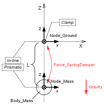
本例題のシミュレーションモデルの設計図を図2に示します。バネが自然長を取っている初期状態でモデルを作成します。
staticなnode「Node_Ground」をグローバル座標系の原点にClampで固定します。マスのnode「Node_Mass」は z = - L = - 1 の位置に定義し、「Node_Ground」との間にin lineおよびprismaticジョイントを設けることによって、「Node_Mass」を z 軸上の1自由度に拘束します。「Node_Ground」と「Node_Mass」の間に、structural internal force「Force_SpringDamper」を定義し、これでバネ力および減衰力を表現します。
“structural internal force”は、2つのnodeの間に作用する力を定義する要素です。structural internal forceのステートメントの型は次のようになります。
   force: <label>,
      { absolute | follower } internal,
         <node1 label>,
            position, <relative arm 1>,
         <node2 label>,
            position, <relative arm 2>,
         <force value>;
ここで、<relative arm>はnodeに対する作用点の相対座標、<force value>はtemplate drive callerで定める力の値です。<force value>の力はnode1に作用し、node2は反作用を受けます。absoluteを選択すると力の向きはグローバル座標系に対して常に一定に保たれ、followerを選択すると力の向きはnode1とともに変化します。
z を「Node_Mass」の z 座標、 vz を「Node_Mass」の z 方向速度とすると、「Force_SpringDamper」がバネ力と減衰力を表現するために発生すべき力は、次の式で与えられます。

この力の定義は、次のように行うことができます。
まず z と vz を“Plugin変数”「DZ」、「VZ」として定義します。
   set: [node, DZ, Node_Mass, structural, string="X[3]"];
   set: [node, VZ, Node_Mass, structural, string="XP[3]"];
Plugin変数の値は各シミュレーションステップで逐一更新されるので、ダイナミックな変数を使用したい場合に有効です。一般に、Plugin変数に代入することができるのは、nodeやelementの“Private Data”です。各nodeまたはelementのPrivate Dataについては公式のInput manualを参照してください。
次に、「Force_SpringDamper」をstring driveを用いて次のように定義します。
   force: Force_SpringDamper,
      follower internal,
         Node_Mass,
            position, null,                               # relative arm
         Node_Ground,
            position, null,                               # relative arm
         single, 0., 0., 1., string, "-K*(DZ-(-L))-C*VZ"; # force value
例題8のバネ‐マス‐ダンパー系の解析を行うための入力ファイルの記述例を以下のコード1に示します。
# spring_mass_damper.mbd

#-----------------------------------------------------------------------------
# [Data Block]

begin: data;
   problem: initial value;
end: data;

#-----------------------------------------------------------------------------
# [<Problem> Block]

begin: initial value;
   initial time:   0.;
   final time:     5.;
   time step:      1.e-3;
   max iterations: 10;
   tolerance:      1.e-6;
end: initial value;

#-----------------------------------------------------------------------------
# [Control Data Block]

begin: control data;
   output frequency: 10;
   structural nodes: 2;
   rigid bodies:     1;
   joints:           3;
   forces:           1;
   gravity;
end: control data;

#-----------------------------------------------------------------------------
# Design Variables
set: real M = 1.;  #[kg] Mass
set: real L = 1.;  #[m] Spring Natural Length
set: real K = 20.; #[N/m] Spring Stiffness Coefficient
set: real C = 1;   #[Ns/m] Damper Damping Coefficient

#-----------------------------------------------------------------------------
# Node Labels
set: integer Node_Ground = 1;
set: integer Node_Mass   = 2;

# Body Labels
set: integer Body_Mass = 1;

# Joint Labels
set: integer JoClamp_Ground      = 1;
set: integer JoInLin_Ground_Mass = 2;
set: integer JoPrism_Ground_Mass = 3;

# Force Labels
set: integer Force_SpringDamper = 1;

#-----------------------------------------------------------------------------
# [Nodes Block]

begin: nodes;

   #-----------------------------------------------------------------------------
   # Nodes
   structural: Node_Ground, static,
      null, # absolute position
      eye,  # absolute orientation
      null, # absolute velocity
      null; # absolute angular velocity

   structural: Node_Mass, dynamic,
      0., 0., -L, # absolute position
      eye,        # absolute orientation
      null,       # absolute velocity
      null;       # absolute angular velocity

end: nodes;

#-----------------------------------------------------------------------------
# Plugin Variables
set: [node, DZ, Node_Mass, structural, string="X[3]"];
set: [node, VZ, Node_Mass, structural, string="XP[3]"];

#-----------------------------------------------------------------------------
# [Elements Block]

begin: elements;

   #-----------------------------------------------------------------------------
   # Bodies
   body: Body_Mass, Node_Mass,
      M,    # mass
      null, # relative center of mass
      eye;  # inertia matrix

   #-----------------------------------------------------------------------------
   # Joints
   joint: JoClamp_Ground,
      clamp,
         Node_Ground,
            null, # absolute position
            eye;  # absolute orientation

   joint: JoInLin_Ground_Mass,
      in line,
         Node_Ground,
            null, # relative line position
            eye,  # relative line orientation
         Node_Mass;

   joint: JoPrism_Ground_Mass,
      prismatic,
         Node_Ground,
         Node_Mass;

   #-----------------------------------------------------------------------------
   # Forces
   force: Force_SpringDamper,
      follower internal,
         Node_Mass,
            position, null,                               # relative arm
         Node_Ground,
            position, null,                               # relative arm
         single, 0., 0., 1., string, "-K*(DZ-(-L))-C*VZ"; # force value

   #-----------------------------------------------------------------------------
   # Gravity
   gravity: 0., 0., -1., const, 9.81;

end: elements;
シミュレーション結果のアニメーションを動画1に示します。