Let's construct a simulation model of a one-dimensional spring-mass-damper system. Two methods to model a spring-damper are discussed. One is a method that uses "structural internal force" in combination with "plugin variable," which is discussed in this chapter. The other is a method that uses "deformable displacement joint," which is discussed in the next chapter.
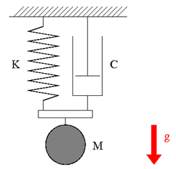
Consider a spring-mass-damper system that is hung from the ceiling as shown in Figure 1. The mass is M=1(kg), the natural length of the spring is L=1(m), and the spring constant is K=20(N/m). The damper applies drag force that is proportional to the magnitude of the velocity with the proportional constant (damping constant) C=1(Ns/m). Construct a simulation model to simulate the motion of the mass when it is released from rest at the position of the spring's natural length. Suppose that the gravity constant is g=9.81(m/s2) and the mass moves along a vertical line.
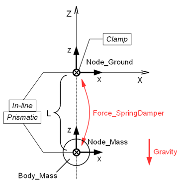
A plan of the simulation model of a spring-mass-damper system for Problem 8 is shown in Figure 2. We construct the model in the configuration where the length of the spring takes its natural length.
The static node "Node_Ground" is defined and is fixed to the origin of the global frame with a clamp joint. The dynamic node "Node_Mass" for the mass is defined at z=-L=-1 and is constrained on the global Z-axis with an in-line joint and a prismatic joint. We define a structural internal force "Force_SpringDamper," between "Node_Ground" and "Node_Mass" and have it express the spring and damper forces.
Structural internal force is an element that can express force acting between two nodes. The syntax for the statement that defines a structural internal force is as follows.
   force: <label>,
      { absolute | follower } internal,
         <node1 label>,
            position, <relative arm 1>,
         <node2 label>,
            position, <relative arm 2>,
         <force value>;
Here, <relative arm 1(2)> is the position of the point of application of the force relative to each node and <force value> is a template drive caller that defines the value of the force. The force defined by <force value> acts on node1 and the reaction force is applied to node2. If absolute is selected, the direction of the force is kept unchanged with respect to the global frame. On the other hand, if follower is selected, the direction of the force changes with node1.
Let z be the Z-position and vz be the Z-velocity of "Node_Mass." Then, the force that "Foce_SpringDamper" must apply in order to express the spring-damper force is given by the following equation.

This force can be defined in the model as follows.
First, we define the plugin variables "DZ" and "VZ" for z and vz, respectively, as follows.
   set: [node, DZ, Node_Mass, structural, string="X[3]"];
   set: [node, VZ, Node_Mass, structural, string="XP[3]"];
The values of plugin variables are updated at each simulation step; therefore they are useful if we want to use dynamic variables in a model. In general, what we can substitute in plugin variables are "private data" of nodes and elements. For information about "private data" of each node and element, refer to the official "Input manual."
Next, "Force_SpringDamper" is defined using a string drive as follows.
   force: Force_SpringDamper,
      follower internal,
         Node_Mass,
            position, null,                               # relative arm
         Node_Ground,
            position, null,                               # relative arm
         single, 0., 0., 1., string, "-K*(DZ-(-L))-C*VZ"; # force value
Code 1 below shows an example input file for the analysis of a spring-mass-damper system for Problem 8.
# spring_mass_damper.mbd

#-----------------------------------------------------------------------------
# [Data Block]

begin: data;
   problem: initial value;
end: data;

#-----------------------------------------------------------------------------
# [<Problem> Block]

begin: initial value;
   initial time:   0.;
   final time:     5.;
   time step:      1.e-3;
   max iterations: 10;
   tolerance:      1.e-6;
end: initial value;

#-----------------------------------------------------------------------------
# [Control Data Block]

begin: control data;
   output frequency: 10;
   structural nodes: 2;
   rigid bodies:     1;
   joints:           3;
   forces:           1;
   gravity;
end: control data;

#-----------------------------------------------------------------------------
# Design Variables
set: real M = 1.;  #[kg] Mass
set: real L = 1.;  #[m] Spring Natural Length
set: real K = 20.; #[N/m] Spring Stiffness Coefficient
set: real C = 1;   #[Ns/m] Damper Damping Coefficient

#-----------------------------------------------------------------------------
# Node Labels
set: integer Node_Ground = 1;
set: integer Node_Mass   = 2;

# Body Labels
set: integer Body_Mass = 1;

# Joint Labels
set: integer JoClamp_Ground      = 1;
set: integer JoInLin_Ground_Mass = 2;
set: integer JoPrism_Ground_Mass = 3;

# Force Labels
set: integer Force_SpringDamper = 1;

#-----------------------------------------------------------------------------
# [Nodes Block]

begin: nodes;

   #-----------------------------------------------------------------------------
   # Nodes
   structural: Node_Ground, static,
      null, # absolute position
      eye,  # absolute orientation
      null, # absolute velocity
      null; # absolute angular velocity

   structural: Node_Mass, dynamic,
      0., 0., -L, # absolute position
      eye,        # absolute orientation
      null,       # absolute velocity
      null;       # absolute angular velocity

end: nodes;

#-----------------------------------------------------------------------------
# Plugin Variables
set: [node, DZ, Node_Mass, structural, string="X[3]"];
set: [node, VZ, Node_Mass, structural, string="XP[3]"];

#-----------------------------------------------------------------------------
# [Elements Block]

begin: elements;

   #-----------------------------------------------------------------------------
   # Bodies
   body: Body_Mass, Node_Mass,
      M,    # mass
      null, # relative center of mass
      eye;  # inertia matrix

   #-----------------------------------------------------------------------------
   # Joints
   joint: JoClamp_Ground,
      clamp,
         Node_Ground,
            null, # absolute position
            eye;  # absolute orientation

   joint: JoInLin_Ground_Mass,
      in line,
         Node_Ground,
            null, # relative line position
            eye,  # relative line orientation
         Node_Mass;

   joint: JoPrism_Ground_Mass,
      prismatic,
         Node_Ground,
         Node_Mass;

   #-----------------------------------------------------------------------------
   # Forces
   force: Force_SpringDamper,
      follower internal,
         Node_Mass,
            position, null,                               # relative arm
         Node_Ground,
            position, null,                               # relative arm
         single, 0., 0., 1., string, "-K*(DZ-(-L))-C*VZ"; # force value

   #-----------------------------------------------------------------------------
   # Gravity
   gravity: 0., 0., -1., const, 9.81;

end: elements;
An animation of the simulation result is shown in Movie 1.