マルチボディダイナミクス解析では、しばしば、衝突や接触を表現することが必要になる場合があります。本項では、一次元の衝突および接触を表現する簡単なモデルを紹介します。
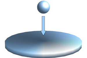
図1のように、ボールが板に向かって飛んでいるとします。ボールは板にどんどん近づいて行き、いずれは板に衝突して跳ね返されるでしょう。あるいはボールの速さが十分に小さければ、板に到達した後、ボールは板の上で接触しながら止まった状態になるかもしれません。このような物体同士が衝突して跳ね返る現象や互いに接触している状態をシミュレーションモデルの上でどのように表現すれば良いでしょうか。
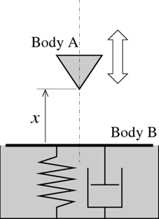
接触を表現する方法の一つとして、接触力をバネとダンパーで表現する方法があります。図2のように、物体Bの接触面に対する物体Aの位置を x とするとき、x > 0 の時には力は働かず、x < 0 の時には x および dx/dt に依存するバネ力および減衰力が物体AとBの間に働きます。
物体Aが物体Bから受ける接触力を数式で表すと次のようになります。
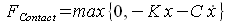
ここで、K はバネ定数、C は減衰定数です。この接触モデルは、衝突と接触を一元的に扱うことができる上に、力を一つ定義するだけなので実施が簡単であるという利点があります。しかし、衝突の瞬間には大きな接触力が急激かつ不連続的に発生するため、数値積分計算が収束しにくくなり、計算コストが増大する、または場合によっては数値積分計算が途中で行き詰ってしまうという難点があります。
この接触力の不連続性を改善するために上のモデルを少し発展させたものが、次の数式で表されるモデルです。

ここで、E と D は定数、fcubstep(&sdot) は図3のグラフに示すように値が 0 から 1 へと滑らかに変化する関数です。fcubstep(&sdot) は、MBDynでは例えば次のように定義できます。
scalar function: "cubstep",
   cubicspline, do not extrapolate,
      -0.03, 0.00,
      -0.02, 0.00,
      -0.01, 0.00,
       0.00, 0.00,
       1.00, 1.00,
       1.01, 1.00,
       1.02, 1.00,
       1.03, 1.00;
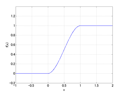
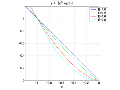
図4には、異なる E の値に対する関数 y = - |x|E sign(x) のグラフを示しています。このグラフより、定数 E を 1 より大きく設定することによって、衝突時のバネ力がより滑らかになることが分かります。また定数 D > 0 を設定することで、fcubstep(-x/D) の効果により、衝突時の減衰力は 0 から連続的に変化するようになります。
計算コストが高いという欠点はありますが、このバネ‐ダンパー接触モデルは様々なケースに応用でき便利です。パラメータ K, C, E, D の値は、通常、シミュレーションの精度と計算コストの両面を考慮して設定します。
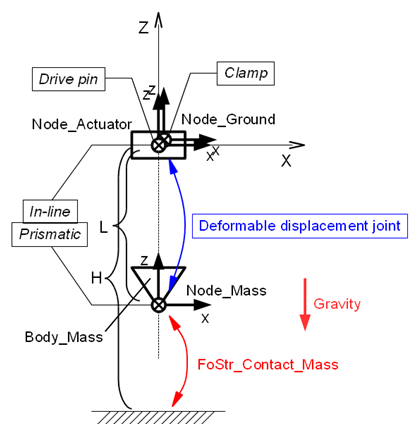
下の動画1は上述の接触モデルを組み込んだシミュレーションモデルのアニメーションです。このシミュレーションモデルは第23項のバネ‐マス‐ダンパー系モデルを部分的に改造したもので、バネの上端に強制変位入力を与え、マスとグラウンドの間に接触力を働かせています。このシミュレーションモデルの設計図を図5に、入力ファイルをコード1に示します。
# elastic_contact_1d.mbd

#-----------------------------------------------------------------------------
# [Data Block]

begin: data;
   problem: initial value;
end: data;

#-----------------------------------------------------------------------------
# [<Problem> Block]

begin: initial value;
   initial time:   0.;
   final time:     4.;
   time step:      1.e-3;
   max iterations: 10;
   tolerance:      1.e-7;
end: initial value;

#-----------------------------------------------------------------------------
# [Control Data Block]

begin: control data;
   use: rigid bodies, gravity, in assembly;
   output frequency: 10;
   structural nodes: 3;
   rigid bodies:     1;
   joints:           5;
   forces:           1;
   gravity;
end: control data;

#-----------------------------------------------------------------------------
# Design Variables
set: real M  = 1.;     # Mass
set: real L  = 1.;     # Spring Natural Length
set: real K  = 40.;    # Spring Stiffness
set: real H  = -1.5;   # Table Position
set: real Kc = 10000.; # Contact Stiffness
set: real Ec = 1.2;    # Contact Stiffness Exponent
set: real Cc = 10.;    # Contact Damping
set: real Dc = 0.0001; # Contact Damping Activation Depth

#-----------------------------------------------------------------------------
# Node Labels
set: integer Node_Actuator = 1;
set: integer Node_Mass     = 2;
set: integer Node_Ground   = 3;

# Body Labels
set: integer Body_Mass = 1;

# Joint Labels
set: integer JoDrivp_Actuator      = 1;
set: integer JoInlin_Actuator_Mass = 2;
set: integer JoPrism_Actuator_Mass = 3;
set: integer JoDfmd_Spring         = 4;
set: integer JoClamp_Ground        = 5;

# Force Labels
set: integer FoStr_Contact_Mass = 1;

#-----------------------------------------------------------------------------
# Scalar Functions
scalar function: "cubstep",
   cubicspline, do not extrapolate,
      -0.03, 0.00,
      -0.02, 0.00,
      -0.01, 0.00,
       0.00, 0.00,
       1.00, 1.00,
       1.01, 1.00,
       1.02, 1.00,
       1.03, 1.00;

#-----------------------------------------------------------------------------
# [Nodes Block]

begin: nodes;

   #-----------------------------------------------------------------------------
   # Nodes
   structural: Node_Actuator, dynamic,
      null, # absolute position
      eye,  # absolute orientation
      null, # absolute velocity
      null; # absolute angular velocity

   structural: Node_Mass, dynamic,
      0., 0., -L, # absolute position
      eye,        # absolute orientation
      null,       # absolute velocity
      null;       # absolute angular velocity

   structural: Node_Ground, static,
      null, # absolute position
      eye,  # absolute orientation
      null, # absolute velocity
      null; # absolute angular velocity

end: nodes;

#-----------------------------------------------------------------------------
# Plugin Variables
set: [node, DZ, Node_Mass, structural, string="X[3]"];
set: [node, VZ, Node_Mass, structural, string="XP[3]"];

#-----------------------------------------------------------------------------
# [Elements Block]

begin: elements;

   #-----------------------------------------------------------------------------
   # Bodies
   body: Body_Mass, Node_Mass,
      M,    # mass
      null, # relative center of mass
      eye;  # inertia matrix

   #-----------------------------------------------------------------------------
   # Joints
   joint: JoDrivp_Actuator,
      drive displacement pin,
         Node_Actuator,
            null,                                           # node offset
            null,                                           # offset
         single, 0., 0., 1., sine, 1., pi/2., -1., one, 0.; # position

   joint: JoInlin_Actuator_Mass,
      in line,
         Node_Actuator,
            null, # relative line position
            eye,  # relative normal direction
         Node_Mass;

   joint: JoPrism_Actuator_Mass,
      prismatic,
         Node_Actuator,
         Node_Mass;

   joint: JoDfmd_Spring,
      deformable displacement joint,
         Node_Actuator,
            null,
         Node_Mass,
            null,
         linear elastic isotropic, K,
         prestrain, single, 0., 0., -1, const, L;

   joint: JoClamp_Ground,
      clamp,
         Node_Ground,
            null, # absolute position
            eye;  # absolute orientation

   #-----------------------------------------------------------------------------
   # Forces
   force: FoStr_Contact_Mass,
      absolute,
         Node_Mass,
            position, null,                                       # relative arm
         single, 0., 0., 1.,
            string, "max(0,Kc*sign(H-DZ)*abs(H-DZ)^Ec
                          -Cc*VZ*model::sf::cubstep((H-DZ)/Dc))"; # force value

   #-----------------------------------------------------------------------------
   # Gravity
   gravity: 0., 0., -1., const, 9.81;

end: elements;