So far in Problem 1 and Problem 2, we considered extremely simple models with only one rigid body and discussed the basic things about MBDyn analyses. Starting from this chapter, we consider more complex models with multiple rigid bodies and joints. In Problem 3 next, we construct a simulation model of a double rigid pendulum. This model includes a "revolute pin" joint and a "revolute hinge" joint.
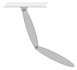
Consider a double rigid pendulum composed of two thin links shown in Figure 1. The mass of each link is M=1.0(kg) and the length of each link is L=1.0(m). Let the initial condition be that the first link is at the horizontal position and the second link is at the vertical-up position with both at rest. Simulate with MBDyn the motion of the pendulum when it is released.
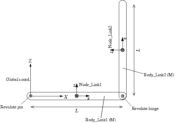
A plan of the simulation model of the double rigid pendulum for Problem 3 is shown in Figure 2. First, we define the global reference frame with the origin at the connection point of the first link and the ceiling, the Z-axis pointing upward, and the X-axis in the horizontal direction in the plane of motion. A structural node is defined for each link ("Node_Link1" and "Node_Link2") at the center of mass with its x-axis in the longitudinal direction. The first link is connected to the global frame with a "revolute pin" and the two links are connected to each other with a "revolute hinge."
In the following, the two joints used in the model, "revolute hinge" and "revolute pin," are briefly described.
This joint constrains two nodes only allowing relative rotation about an axis. The basic syntax for the statement that defines a revolute hinge is as follows.
   joint: <label>,
      revolute hinge,
         <node 1>,
            <relative offset 1>,
            hinge, <relative orientation matrix 1>,
         <node 2>,
            <relative offset 2>,
            hinge, <relative orientation matrix 2>;
Here, the axis of rotation is the z-axis of the relative frames defined by <relative offset 1> and <relative orientation matrix 1>, and <relative offset 2> and <relative orientation matrix 2>. The two relative frames have to be consistent.
This joint constrains a node only allowing absolute rotation about an axis. The basic syntax for the statement that defines a revolute pin is as follows.
   joint: <label>,
      revolute pin,
         <node 1>,
            <relative offset>,
            hinge, <relative orientation matrix>,
            <absolute pin position>,
            hinge, <absolute pin orientation matrix>;
Here, the axis of rotation is the z-axis of the relative frames defined by <relative offset> and <relative orientation matrix>, and <absolute pin position> and <absolute pin orientation matrix>. The two relative frames have to be consistent.
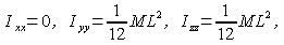
If thickness of the link is ignored, the moments of inertia of the link about the center of mass with respect to the node are given as follows.
An example input file for the analysis of the double rigid pendulum of Problem 3 is shown in Code 1.
# double_rigid_pendulum.mbd

begin: data;
   problem: initial value;
end: data;

begin: initial value;
   initial time:   0.;
   final time:     5.;
   time step:      1.e-3;
   max iterations: 10;
   tolerance:      1.e-6;
end: initial value;

begin: control data;
   structural nodes: 2;
   rigid bodies:     2;
   joints:           2;
   gravity;
end: control data;

# Design Variables
set: real M = 1.; # Mass of Link1 and Link2
set: real L = 1.; # Length of Link1 and Link2

# Node Labels
set: integer Node_Link1 = 1;
set: integer Node_Link2 = 2;

# Body Labels
set: integer Body_Link1 = 1;
set: integer Body_Link2 = 2;

# Joint Labels
set: integer JoRevp_Link1       = 1;
set: integer JoRevh_Link1_Link2 = 2;

begin: nodes;
   structural: Node_Link1, dynamic,
      1./2.*L, 0., 0., # absolute position
      eye,             # absolute orientation
      null,            # absolute velocity
      null;            # absolute angular velocity

   structural: Node_Link2, dynamic,
      L, 0., 1./2.*L,        # absolute position
      euler, 0., -pi/2., 0., # absolute orientation
      null,                  # absolute velocity
      null;                  # absolute angular velocity

end: nodes;

begin: elements;
   body: Body_Link1, Node_Link1,
      M,                                # mass
      null,                             # relative center of mass
      diag, 0., M*L^2./12., M*L^2./12.; # inertia matrix

   body: Body_Link2, Node_Link2,
      M,                                # mass
      null,                             # relative center of mass
      diag, 0., M*L^2./12., M*L^2./12.; # inertia matrix

   joint: JoRevp_Link1,
      revolute pin,
         Node_Link1,
            -1./2.*L, 0., 0.,                    # relative offset
            hinge, 1, 1., 0., 0., 3, 0., 1., 0., # relative axis orientation
            null,                                # absolute pin position
            hinge, 1, 1., 0., 0., 3, 0., 1., 0.; # absolute pin orientation

   joint: JoRevh_Link1_Link2,
      revolute hinge,
         Node_Link1,
            1./2.*L, 0., 0.,                     # relative offset
            hinge, 1, 1., 0., 0., 3, 0., 1., 0., # relative axis orientation
         Node_Link2,
            -1./2.*L, 0., 0.,                    # relative offset
            hinge, 1, 1., 0., 0., 3, 0., 1., 0.; # relative axis orientation

   gravity: 0., 0., -1., const, 9.81;

end: elements;
An animation of the simulation result is shown in Movie 1.