The simulation model of a double rigid pendulum we constructed in the last chapter lacks versatility in the sense that it can only allow simulations with a fixed initial configuration. Let us now reform the model so that it can allow simulations with various initial configurations. Here, we utilize "reference," which is convenient when we construct a complex model.
Similarly to Problem 3 in the last chapter, consider a double rigid pendulum composed of two links. Let the angle between Link1 and the vertical line be θ1 and the angle between Link2 and Link1 be θ2. Create an MBDyn input file to simulate the motion of the pendulum with arbitrary initial angles θ1 and θ2.
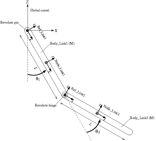
A plan of the simulation model of the double rigid pendulum for Problem 4 is shown in Figure 1. With initial angles θ1 and θ2 as variables, we construct a model in a general configuration. A structural node is defined for each link ("Node_Link1" and "Node_Link2") at the center of mass with its x-axis in the longitudinal direction. Link1 is connected to the global frame with a "revolute pin" and the two links are connected to each other with a "revolute hinge." Construction of the model becomes easier if we define two "references" "Ref_Link1" and "Ref_Link2" as shown in the figure.
Reference is a reference frame that can be freely defined for our convenience in model construction. The syntax for the statement that defines a reference is as follows.
   reference: <label> ,
      <absolute position> ,
      <absolute orientation matrix> ,
      <absolute velocity> ,
      <absolute angular velocity> ;
A reference can be defined anywhere in the input file (even outside of a block). Once we define a reference, we can refer to it when we enter the following values in statements such as the ones defining nodes and joints.
When we want to enter these values referring to an existing reference, we use the keyword "reference" and write as follows.
reference, <reference label>, <value>
A procedure to define the nodes "Node_Link1" and "Node_Link2" for the two links of the model utilizing references is described as follows.
First, we define a reference "Ref_Link1." ("Ref_Link1" is obtained by rotating the global frame by π/2-θ1 about the y-axis.)
   set: integer Ref_Link1 = 1;

   reference: Ref_Link1,
      null,                        # absolute position
      euler, 0., pi/2.-theta1, 0., # absolute orientation
      null,                        # absolute velocity
      null;                        # absolute angular velocity
Next, referring to the reference "Ref_Link1," we define the node "Node_Link1." ("Node_Link1" is obtained by translating "Ref_Link1" by L/2 in its x direction.)
   set: integer Node_Link1 = 1;

   structural: Node_Link1, dynamic,
      reference, Ref_Link1, 1./2.*L, 0., 0., # absolute position
      reference, Ref_Link1, eye,             # absolute orientation
      reference, Ref_Link1, null,            # absolute velocity
      reference, Ref_Link1, null;            # absolute angular velocity
It is possible to define a new reference referring to an existing reference. Here, we define the reference "Ref_Link2" referring to the reference "Ref_Link1." ("Ref_Link2" is obtained by translating "Ref_Link1" by L in its x-direction and rotating it by -θ2 about its y-axis.)
   set: integer Ref_Link2 = 2;

   reference: Ref_Link2,
      reference, Ref_Link1, L, 0., 0.,              # absolute position
      reference, Ref_Link1, euler, 0., -theta2, 0., # absolute orientation
      reference, Ref_Link1, null,                   # absolute velocity
      reference, Ref_Link1, null;                   # absolute angular velocity
Finally, the node "Node_Link2" is defined referring to the reference "Ref_Link2." ("Node_Link2" is obtained by translating "Ref_Link2" by L/2 in its x-direction.)
   set: integer Node_Link2 = 2;

   structural: Node_Link2, dynamic,
      reference, Ref_Link2, 1./2.*L, 0., 0., # absolute position
      reference, Ref_Link2, eye,             # absolute orientation
      reference, Ref_Link2, null,            # absolute velocity
      reference, Ref_Link2, null;            # absolute angular velocity
It is possible and perfectly OK to define the nodes "Node_Link1" and "Node_Link2" without using references. For example, since the absolute position of the node "Node_Link2" is

we can define "Node_Link2" as follows. But it is easier and simpler if we use references as above.
   set: integer Node_Link2 = 2;

   structural: Node_Link2, dynamic,
      L*sin(theta1)+L*sin(theta1+theta2), 0., -L*cos(theta1)-L*cos(theta1+theta2), # absolute position
      euler, 0., pi-(theta1+theta2), 0., # absolute orientation
      null,                              # absolute velocity
      null;                              # absolute angular velocity
An example input file for Problem 4 is shown in Code 1 below.
# double_rigid_pendulum_2.mbd

begin: data;
   problem: initial value;
end: data;

begin: initial value;
   initial time:   0.;
   final time:     5.;
   time step:      1.e-3;
   max iterations: 10;
   tolerance:      1.e-6;
end: initial value;

begin: control data;
   structural nodes: 2;
   rigid bodies:     2;
   joints:           2;
   gravity;
end: control data;

# Design Variables
set: real M = 1.; # Mass of Link1 and Link2
set: real L = 1.; # Length of Link1 and Link2

set: real theta1 = pi/6.; # Initial angle of Link1 w.r.t vertical line
set: real theta2 = pi/6.; # Initial angle of Link2 w.r.t Link1

# Reference Labels
set: integer Ref_Link1 = 1;
set: integer Ref_Link2 = 2;

# Node Labels
set: integer Node_Link1 = 1;
set: integer Node_Link2 = 2;

# Body Labels
set: integer Body_Link1 = 1;
set: integer Body_Link2 = 2;

# Joint Labels
set: integer JoRevp_Link1       = 1;
set: integer JoRevh_Link1_Link2 = 2;

# Reference
reference: Ref_Link1,
   null,                        # absolute position
   euler, 0., pi/2.-theta1, 0., # absolute orientation
   null,                        # absolute velocity
   null;                        # absolute angular velocity

reference: Ref_Link2,
   reference, Ref_Link1, L, 0., 0.,              # absolute position
   reference, Ref_Link1, euler, 0., -theta2, 0., # absolute orientation
   reference, Ref_Link1, null,                   # absolute velocity
   reference, Ref_Link1, null;                   # absolute angular velocity

begin: nodes;
   structural: Node_Link1, dynamic,
      reference, Ref_Link1, 1./2.*L, 0., 0., # absolute position
      reference, Ref_Link1, eye,             # absolute orientation
      reference, Ref_Link1, null,            # absolute velocity
      reference, Ref_Link1, null;            # absolute angular velocity

   structural: Node_Link2, dynamic,
      reference, Ref_Link2, 1./2.*L, 0., 0., # absolute position
      reference, Ref_Link2, eye,             # absolute orientation
      reference, Ref_Link2, null,            # absolute velocity
      reference, Ref_Link2, null;            # absolute angular velocity

end: nodes;

begin: elements;
   body: Body_Link1, Node_Link1,
      M,                                # mass
      null,                             # relative center of mass
      diag, 0., M*L^2./12., M*L^2./12.; # inertia matrix

   body: Body_Link2, Node_Link2,
      M,                                # mass
      null,                             # relative center of mass
      diag, 0., M*L^2./12., M*L^2./12.; # inertia matrix

   joint: JoRevp_Link1,
      revolute pin,
         Node_Link1,
            reference, Ref_Link1, null,                                # relative offset
            hinge, reference, Ref_Link1, 1, 1., 0., 0., 3, 0., 1., 0., # relative axis orientation
            reference, Ref_Link1, null,                                # absolute pin position
            hinge, reference, Ref_Link1, 1, 1., 0., 0., 3, 0., 1., 0.; # absolute pin orientation

   joint: JoRevh_Link1_Link2,
      revolute hinge,
         Node_Link1,
            reference, Ref_Link2, null,                                # relative offset
            hinge, reference, Ref_Link2, 1, 1., 0., 0., 3, 0., 1., 0., # relative axis orientation
         Node_Link2,
            reference, Ref_Link2, null,                                # relative offset
            hinge, reference, Ref_Link2, 1, 1., 0., 0., 3, 0., 1., 0.; # relative axis orientation

   gravity: 0., 0., -1., const, 9.81;

end: elements;
An animation of the simulation result with initial angles θ1 and θ2 both being π/6 is shown in Movie 1.