We continue to construct the simulation model of a crank-slider mechanism. In this chapter, in particular, we focus on how we can wind the crank by means of "axial rotation" joint and "drive caller." An example input file and an animation of a simulation result is presented at the end of this chapter.
This joint imposes a constraint equivalent to a revolute pin (see Chapter 14) and also imposes arbitrary angular velocity between two nodes. The basic syntax for the statement that defines an axial rotation is as follows.
   joint: <label>,
      axial rotation,
         <node 1>,
            <relative offset 1>,
            hinge, <relative orientation matrix 1>,
         <node 2>,
            <relative offset 2>,
            hinge, <relative orientation matrix 2>,
         <angular velocity>;
Here, the axis of rotation is the z-axis of the relative frames defined by <relative offset 1> and <relative orientation matrix 1>, and <relative offset 2> and <relative orientation matrix 2>. The two relative frames have to be consistent. <angular velocity> is specified by an object called "drive caller," which is explained below.
When it is necessary to provide a time-dependent input to an element that defines a motion or a force, an object called drive caller is used. A drive caller is basically a scalar function of time. Depending on the type of drive caller, the time-dependence may be explicit or implicit. (In implicit case, a drive caller provides an input that depends on a state of the model, in effect, forming a feedback.) Examples of drive callers are "sine drive," which provides a sine input, and "constant drive," which provides a constant input. The most general "string drive" can provide an arbitrary explicit or implicit time-dependent input (see Chapter 22). There is also "file drive" that can input time-series data written in a file. There are many kinds of drive callers. Refer to the official "Input manual" for more information.
In our current example problem, we use "ramp drive" for the angular velocity input to the axial rotation joint. The syntax of a ramp drive is as follows. (See Figure 1.)
   ramp,
      <slope>,
      <initial time>,
      { forever | <final time> },
      <initial value>
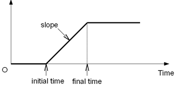
For our simulation model of a crank-slider mechanism, we connect the node for the crank "Node_Crank" to the node "Node_Ground" with an axial rotation joint and provide an angular velocity input by means of a ramp drive. We increase the angular velocity from 0 to 2π(rad/s) in the first one second and keep it constant after that.
set: integer JoAxrot_Ground_Crank  = 2;

joint: JoAxrot_Ground_Crank,
   axial rotation,
      Node_Ground,
         null,                     # relative offset
         hinge, eye,               # relative orientation
      Node_Crank,
         -Length_Crank/2., 0., 0., # relative offset
         hinge, eye,               # relative orientation
      ramp, 2.*pi, 0., 1., 0.;     # angular velocity
An example input file for the analysis of the crank-slider mechanism of Problem 5 is shown in Code 1 below. Because this code has many lines, separator lines are used to make the code easier to read.
# crank_slider.mbd

#-----------------------------------------------------------------------------
# [Data Block]

begin: data;
   problem: initial value;
end: data;

#-----------------------------------------------------------------------------
# [<Problem> Block]

begin: initial value;
   initial time:   0.;
   final time:     5.;
   time step:      1.e-2;
   max iterations: 10;
   tolerance:      1.e-6;
end: initial value;

#-----------------------------------------------------------------------------
# [Control Data Block]

begin: control data;
   structural nodes: 4;
   rigid bodies:     3;
   joints:           6;
end: control data;

#-----------------------------------------------------------------------------
# Design Variables
set: real Mass_Crank    = 1.;
set: real Mass_Conrod   = 1.;
set: real Mass_Slider   = 1.;
set: real Length_Crank  = 0.2;
set: real Length_Conrod = 0.4;
set: real Offset_Slider = 0.05;

#-----------------------------------------------------------------------------
# Reference Labels
set: integer Ref_Conrod = 1;

# Node Labels
set: integer Node_Ground = 1;
set: integer Node_Crank  = 2;
set: integer Node_Conrod = 3;
set: integer Node_Slider = 4;

# Body Labels
set: integer Body_Crank  = 1;
set: integer Body_Conrod = 2;
set: integer Body_Slider = 3;

# Joint Labels
set: integer JoClamp_Ground        = 1;
set: integer JoAxrot_Ground_Crank  = 2;
set: integer JoRevh_Crank_Conrod   = 3;
set: integer JoInlin_Conrod_Slider = 4;
set: integer JoInlin_Ground_Slider = 5;
set: integer JoPrism_Ground_Slider = 6;

#-----------------------------------------------------------------------------
# Intermediate Variables
set: real Izz_Crank  = Mass_Crank*Length_Crank^2./12.;
set: real Izz_Conrod = Mass_Conrod*Length_Conrod^2./12.;

#-----------------------------------------------------------------------------
# References
reference: Ref_Conrod,
   Length_Crank, 0., 0.,                             # absolute position
   euler, 0., 0., asin(Offset_Slider/Length_Conrod), # absolute orientation
   null,                                             # absolute velocity
   null;                                             # absolute angular velocity

#-----------------------------------------------------------------------------
# [Nodes Block]

begin: nodes;

   #-----------------------------------------------------------------------------
   # Nodes
   structural: Node_Ground, static,
      0., 0., 0., # absolute position
      eye,        # absolute orientation
      null,       # absolute velocity
      null;       # absolute angular velocity

   structural: Node_Crank, dynamic,
      Length_Crank/2., 0., 0., # absolute position
      eye,                     # absolute orientation
      null,                    # absolute velocity
      null;                    # absolute angular velocity

   structural: Node_Conrod, dynamic,
      reference, Ref_Conrod, Length_Conrod/2., 0., 0., # absolute position
      reference, Ref_Conrod, eye,                      # absolute orientation
      null,                                            # absolute velocity
      null;                                            # absolute angular velocity

   structural: Node_Slider, dynamic,
      reference, Ref_Conrod, Length_Conrod, 0., 0., # absolute position
      eye,                                          # absolute orientation
      null,                                         # absolute velocity
      null;                                         # absolute angular velocity

end: nodes;

#-----------------------------------------------------------------------------
# [Elements Block]

begin: elements;

   #-----------------------------------------------------------------------------
   # Bodies
   body: Body_Crank, Node_Crank,
      Mass_Crank,              # mass
      null,                    # relative center of mass
      diag, 1., 1., Izz_Crank; # inertia matrix

   body: Body_Conrod, Node_Conrod,
      Mass_Conrod,              # mass
      null,                     # relative center of mass
      diag, 1., 1., Izz_Conrod; # inertia matrix

   body: Body_Slider, Node_Slider,
      Mass_Slider, # mass
      null,        # relative center of mass
      eye;         # inertia matrix

   #-----------------------------------------------------------------------------
   # Joints
   joint: JoClamp_Ground,
      clamp,
         Node_Ground,
            null, # absolute position
            eye;  # absolute orientation

   joint: JoAxrot_Ground_Crank,
      axial rotation,
         Node_Ground,
            null,                     # relative offset
            hinge, eye,               # relative orientation
         Node_Crank,
            -Length_Crank/2., 0., 0., # relative offset
            hinge, eye,               # relative orientation
         ramp, 2.*pi, 0., 1., 0.;     # angular velocity

   joint: JoRevh_Crank_Conrod,
      revolute hinge,
         Node_Crank,
            reference, Ref_Conrod, null,       # relative offset
            hinge, reference, Ref_Conrod, eye, # relative axis orientation
         Node_Conrod,
            reference, Ref_Conrod, null,       # relative offset
            hinge, reference, Ref_Conrod, eye; # relative axis orientation

   joint: JoInlin_Conrod_Slider,
      in line,
         Node_Conrod,
            Length_Conrod/2., 0., 0., # relative line position
            eye,                      # relative orientation
         Node_Slider;

   joint: JoInlin_Ground_Slider,
      in line,
         Node_Ground,
            0., Offset_Slider, 0.,         # relative line position
            1, 0., 0., -1., 3, 1., 0., 0., # relative orientation
         Node_Slider;

   joint: JoPrism_Ground_Slider,
      prismatic,
         Node_Ground,
         Node_Slider;

end: elements;
An animation of the simulation result is shown in Movie 1.