This chapter introduces "structural force" element, which can be used to express a general external force, and also explains about "template drive caller" object, which is required to define a structural force.
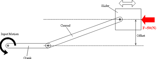
Consider the simulation model of a crank-slider mechanism that we constructed in Problem 5. Modify the model so that the slider is subject to an external force as shown in Figure 1.
An external force is expressed by a "structural force" element. The syntax for the statement that defines a structural force is as follows.
   force: <label>,
      { absolute | follower },
         <node label>,
            position, <relative arm>,
            <force value>;
Here, <node label> is the label of a node to which the force is applied and <relative arm> is the position of the point of application of the force relative to the node. <force value> is specified by means of a "template drive caller" object, which is described below.
Either absolute or follower is selected. If absolute is selected, the direction of the force is kept unchanged with respect to the global frame. On the other hand, if follower is selected, the direction of the force changes with the node.
Drive caller, which was introduced in Chapter 18, is a time-dependent scalar, thus one-dimensional, input. "Template drive caller" is used when a multi-dimensional input is required, for example, when a three-dimensional or a six-dimensional vector input is required. There are the following four types of template drive callers.
null represents a null vector and means "no input."
single is written as follows and defines a multi-dimensional vector input by a constant directional vector and a variable gain.
   single,
      <entity>, <drive caller>
Here, <entity> is a constant directional vector and <drive caller> defines a time-dependent gain.
component is written as follows and defines a multi-dimensional input component by component. In this case, as many drive callers as dimensions are required.
   component,
      { inactive | <drive caller> }, { inactive | <drive caller> }, ...
We skip array here.
We add a "structural force" that represents a constant force of 50(N) on the slider to the crank-slider model of Problem 5. Since the slider has only one degree of freedom, the point of application of the force can be anywhere. It would be simple if we choose the point of application at "Node_Slider." The following statements define the force on the slider in -x direction by means of a template drive caller of the type single.
set: integer FoStr_Slider = 1;

force: FoStr_Slider,
   absolute,
      Node_Slider,
         position, null,              # relative arm
         single, -1, 0, 0, const, 50; # force value
Code 1 below shows an example input file for the analysis of the crank-slider mechanism of Problem 6, which includes the added external force on the slider. The code is almost the same as the one for Problem 5 except the last part where the structural force element is added. Note that there is also a slight change in the control data block where the forces term has been added.
# crank_slider_2.mbd

#-----------------------------------------------------------------------------
# [Data Block]

begin: data;
   problem: initial value;
end: data;

#-----------------------------------------------------------------------------
# [<Problem> Block]

begin: initial value;
   initial time:   0.;
   final time:     5.;
   time step:      1.e-2;
   max iterations: 10;
   tolerance:      1.e-6;
end: initial value;

#-----------------------------------------------------------------------------
# [Control Data Block]

begin: control data;
   structural nodes: 4;
   rigid bodies:     3;
   joints:           6;
   forces:           1;
end: control data;

#-----------------------------------------------------------------------------
# Design Variables
set: real Mass_Crank    = 1.;
set: real Mass_Conrod   = 1.;
set: real Mass_Slider   = 1.;
set: real Length_Crank  = 0.2;
set: real Length_Conrod = 0.4;
set: real Offset_Slider = 0.05;

#-----------------------------------------------------------------------------
# Reference Labels
set: integer Ref_Conrod = 1;

# Node Labels
set: integer Node_Ground = 1;
set: integer Node_Crank  = 2;
set: integer Node_Conrod = 3;
set: integer Node_Slider = 4;

# Body Labels
set: integer Body_Crank  = 1;
set: integer Body_Conrod = 2;
set: integer Body_Slider = 3;

# Joint Labels
set: integer JoClamp_Ground        = 1;
set: integer JoAxrot_Ground_Crank  = 2;
set: integer JoRevh_Crank_Conrod   = 3;
set: integer JoInlin_Conrod_Slider = 4;
set: integer JoInlin_Ground_Slider = 5;
set: integer JoPrism_Ground_Slider = 6;

# Force Labels
set: integer FoStr_Slider = 1;

#-----------------------------------------------------------------------------
# Intermediate Variables
set: real Izz_Crank  = Mass_Crank*Length_Crank^2./12.;
set: real Izz_Conrod = Mass_Conrod*Length_Conrod^2./12.;

#-----------------------------------------------------------------------------
# References
reference: Ref_Conrod,
   Length_Crank, 0., 0.,                             # absolute position
   euler, 0., 0., asin(Offset_Slider/Length_Conrod), # absolute orientation
   null,                                             # absolute velocity
   null;                                             # absolute angular velocity

#-----------------------------------------------------------------------------
# [Nodes Block]

begin: nodes;

   #-----------------------------------------------------------------------------
   # Nodes
   structural: Node_Ground, static,
      0., 0., 0., # absolute position
      eye,        # absolute orientation
      null,       # absolute velocity
      null;       # absolute angular velocity

   structural: Node_Crank, dynamic,
      Length_Crank/2., 0., 0., # absolute position
      eye,                     # absolute orientation
      null,                    # absolute velocity
      null;                    # absolute angular velocity

   structural: Node_Conrod, dynamic,
      reference, Ref_Conrod, Length_Conrod/2., 0., 0., # absolute position
      reference, Ref_Conrod, eye,                      # absolute orientation
      null,                                            # absolute velocity
      null;                                            # absolute angular velocity

   structural: Node_Slider, dynamic,
      reference, Ref_Conrod, Length_Conrod, 0., 0., # absolute position
      eye,                                          # absolute orientation
      null,                                         # absolute velocity
      null;                                         # absolute angular velocity

end: nodes;

#-----------------------------------------------------------------------------
# [Elements Block]

begin: elements;

   #-----------------------------------------------------------------------------
   # Bodies
   body: Body_Crank, Node_Crank,
      Mass_Crank,              # mass
      null,                    # relative center of mass
      diag, 1., 1., Izz_Crank; # inertia matrix

   body: Body_Conrod, Node_Conrod,
      Mass_Conrod,              # mass
      null,                     # relative center of mass
      diag, 1., 1., Izz_Conrod; # inertia matrix

   body: Body_Slider, Node_Slider,
      Mass_Slider, # mass
      null,        # relative center of mass
      eye;         # inertia matrix

   #-----------------------------------------------------------------------------
   # Joints
   joint: JoClamp_Ground,
      clamp,
         Node_Ground,
            null, # absolute position
            eye;  # absolute orientation

   joint: JoAxrot_Ground_Crank,
      axial rotation,
         Node_Ground,
            null,                     # relative offset
            hinge, eye,               # relative orientation
         Node_Crank,
            -Length_Crank/2., 0., 0., # relative offset
            hinge, eye,               # relative orientation
         ramp, 2.*pi, 0., 1., 0.;     # angular velocity

   joint: JoRevh_Crank_Conrod,
      revolute hinge,
         Node_Crank,
            reference, Ref_Conrod, null,       # relative offset
            hinge, reference, Ref_Conrod, eye, # relative axis orientation
         Node_Conrod,
            reference, Ref_Conrod, null,       # relative offset
            hinge, reference, Ref_Conrod, eye; # relative axis orientation

   joint: JoInlin_Conrod_Slider,
      in line,
         Node_Conrod,
            Length_Conrod/2., 0., 0., # relative line position
            eye,                      # relative orientation
         Node_Slider;

   joint: JoInlin_Ground_Slider,
      in line,
         Node_Ground,
            0., Offset_Slider, 0.,         # relative line position
            1, 0., 0., -1., 3, 1., 0., 0., # relative orientation
         Node_Slider;

   joint: JoPrism_Ground_Slider,
      prismatic,
         Node_Ground,
         Node_Slider;

   #-----------------------------------------------------------------------------
   # Forces
   force: FoStr_Slider,
      absolute,
         Node_Slider,
            position, null,              # relative arm
            single, -1, 0, 0, const, 50; # force value

end: elements;