When a rigid body is spinning about an axis, if there is an external input of angular velocity that swings the axis of the spin, then a rotational moment arises in the direction perpendicular to both the swinging angular velocity and the axis of the spin. This rotational moment is called gyro moment. You have probably seen before in a classroom or at a science museum an experiment to experience the gyro moment by tilting a spinning wheel on a turntable (see movie>>). Let's construct a simulation model of a machine that mimics such an experiment.
Construct a simulation model of the gyro-moment experiment machine shown in Figure 1. The stage can freely turn horizontally without friction. The arm is connected to the stage and the wheel is connected to the arm. The wheel spins at a constant rate. The arm can turn in a vertical plane relative to the stage and the angle of the arm can be changed arbitrarily by a motor.
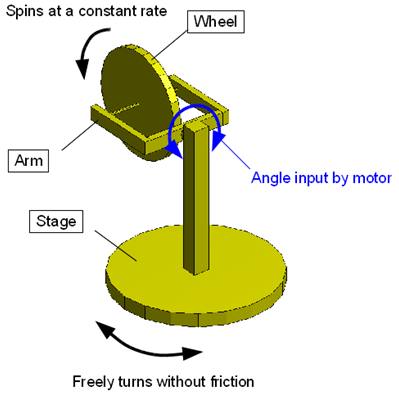
Figure 2 shows a plan of the simulation model of the gyro-moment experiment machine. In the figure, "Ref_Wheel_Spindle" is slightly displaced from "Node_Wheel" but they are actually at the same location.
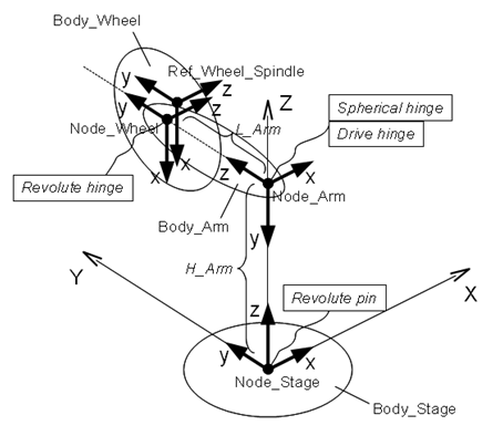
For the sake of convenience, each node is defined with its z-axis parallel to the axis of rotation of its associated part. The arm and the stage are connected to each other with a "spherical hinge" joint and a "drive hinge" joint. The spherical hinge constrains the relative position and the drive hinge constrains the relative orientation. Drive hinge is explained in the following section. Note that if the spherical hinge is replaced with a revolute hinge (as our intuition might suggest), the model becomes over-constrained. (But it is possible to use a revolute hinge if it is used in combination with a "total joint" instead of the drive hinge.)
This joint constrains the relative orientation of two nodes (the relative position is not constrained) and can impose an arbitrary time-dependent relative angle between the nodes. The time-dependent relative angle is defined by means of a template drive caller. The basic syntax for the statement that defines a drive hinge is as follows.
   joint: <label>,
      drive hinge,
         <node 1>,
            hinge, <relative orientation matrix 1>,
         <node 2>,
            hinge, <relative orientation matrix 2>,
         <hinge orientation>;
Here, in <hinge orientation> we set a desired time-dependent relative angle by means of a template drive caller.
In our current example problem, we use a drive hinge to express the motor that changes the angle of the arm.
Since we want to input an arbitrary time-dependent angle of the arm, we choose to use a "scalar function drive" for the drive caller input <hinge orientation> of the drive hinge. Scalar function drive is a drive caller that can provide an arbitrary scalar function input. The syntax for a scalar function drive is as follows.
   scalar function, "<scalar function name>",
      ,<scalar function definition>
Now, suppose we want to input the angle of the arm as shown in Figure 3. Since the function shown in Figure 3 is a multi-linear function, it can be defined in MBDyn by the scalar function called "multilinear."
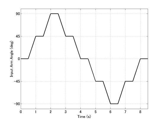
The definition of the drive hinge that imposes the angle of the arm shown in Figure 3 by means of a scalar function drive is in the following. A template drive caller of the type single is used to define the angle input about the z-axis of the "Node_Arm." Note that the unit of the angle is a radian.
set: integer JoDrivh_Stage_Arm = 3;

joint: JoDrivh_Stage_Arm,
   drive hinge,
      Node_Stage,
         hinge, euler, -pi/2., 0., 0.,                      # relative axis orientation
      Node_Arm,
         hinge, eye,                                        # relative axis orientation
      single, 0., 0., 1., scalar function, "Fun_Arm_Input", # position
         multilinear,
            0.0, 0.,
            0.5, 0.,
            1.0, pi/4.,
            1.5, pi/4.,
            2.0, pi/2.,
            2.5, pi/2.,
            3.0, pi/4.,
            3.5, pi/4.,
            4.0, 0,
            4.5, 0,
            5.0, -pi/4.,
            5.5, -pi/4.,
            6.0, -pi/2.,
            6.5, -pi/2.,
            7.0, -pi/4.,
            7.5, -pi/4.,
            8.0, 0.,
            8.5, 0.;
An example input file for the analysis of the gyro-moment experiment machine of Problem 7 is shown in Code 1 below.
# gyro_moment.mbd

#-----------------------------------------------------------------------------
# [Data Block]

begin: data;
   problem: initial value;
end: data;

#-----------------------------------------------------------------------------
# [<Problem> Block]

begin: initial value;
   initial time:   0.;
   final time:     8.5;
   time step:      1.e-3;
   max iterations: 10;
   tolerance:      1.e-6;
end: initial value;

#-----------------------------------------------------------------------------
# [Control Data Block]

begin: control data;
   output frequency: 10;
   structural nodes: 3;
   rigid bodies:     3;
   joints:           4;
end: control data;

#-----------------------------------------------------------------------------
# Design Variables

set: real I_Stage = 0.1;   #[kg m^2]  Moment of Inertia of Stage
set: real M_Wheel = 3.;    #[kg] Mass of Wheel
set: real R_Wheel = 0.4;   #[m] Radius of Wheel
set: real H_Arm   = 1.;    #[m] Height of Arm
set: real L_Arm   = 0.6;   #[m] Length of Arm
set: real W_Wheel = 10*pi; #[rad/s] Angular Velocity of Wheel

#-----------------------------------------------------------------------------
# Reference Labels
set: integer Ref_Wheel_Spindle = 1;

# Node Labels
set: integer Node_Stage = 1;
set: integer Node_Arm   = 2;
set: integer Node_Wheel = 3;

# Body Labels
set: integer Body_Stage = 1;
set: integer Body_Arm   = 2;
set: integer Body_Wheel = 3;

# Joint Labels
set: integer JoRevp_Stage      = 1;
set: integer JoSphh_Stage_Arm  = 2;
set: integer JoDrivh_Stage_Arm = 3;
set: integer JoRevh_Arm_Wheel  = 4;

#-----------------------------------------------------------------------------
# Intermediate Variables
set: real Ixx_Wheel = M_Wheel*R_Wheel^2./4.;
set: real Iyy_Wheel = M_Wheel*R_Wheel^2./4.;
set: real Izz_Wheel = M_Wheel*R_Wheel^2./2.;

#-----------------------------------------------------------------------------
# References
reference: Ref_Wheel_Spindle,
   0., L_Arm, H_Arm,     # absolute position
   euler, 0., pi/2., 0., # absolute orientation
   null,                 # absolute velocity
   null;                 # absolute angular velocity

#-----------------------------------------------------------------------------
# [Nodes Block]

begin: nodes;

   #-----------------------------------------------------------------------------
   # Nodes
   structural: Node_Stage, dynamic,
      null, # absolute position
      eye,  # absolute orientation
      null, # absolute velocity
      null; # absolute angular velocity

   structural: Node_Arm, dynamic,
      0., 0., H_Arm,         # absolute position
      euler, -pi/2., 0., 0., # absolute orientation
      null,                  # absolute velocity
      null;                  # absolute angular velocity

   structural: Node_Wheel, dynamic,
      reference, Ref_Wheel_Spindle, null,             # absolute position
      reference, Ref_Wheel_Spindle, eye,              # absolute orientation
      reference, Ref_Wheel_Spindle, null,             # absolute velocity
      reference, Ref_Wheel_Spindle, 0., 0., -W_Wheel; # absolute angular velocity

end: nodes;

#-----------------------------------------------------------------------------
# [Elements Block]

begin: elements;

   #-----------------------------------------------------------------------------
   # Bodies
   body: Body_Stage, Node_Stage,
      1.,                    # mass
      null,                  # relative center of mass
      diag, 1., 1., I_Stage; # inertia matrix

   body: Body_Arm, Node_Arm,
      1.,                        # mass
      null,                      # relative center of mass
      diag, 1.e-6, 1.e-6, 1.e-6; # inertia matrix

   body: Body_Wheel, Node_Wheel,
      M_Wheel,                               # mass
      null,                                  # relative center of mass
      diag, Ixx_Wheel, Iyy_Wheel, Izz_Wheel; # inertia matrix

   #-----------------------------------------------------------------------------
   # Joints
   joint: JoRevp_Stage,
      revolute pin,
         Node_Stage,
            null, # relative offset
            null; # absolute pin position

   joint: JoSphh_Stage_Arm,
      spherical hinge,
         Node_Stage,
            0., 0., H_Arm, # relative offset
         Node_Arm,
            null;          # relative offset

   joint: JoDrivh_Stage_Arm,
      drive hinge,
         Node_Stage,
            hinge, euler, -pi/2., 0., 0.,                      # relative axis orientation
         Node_Arm,
            hinge, eye,                                        # relative axis orientation
         single, 0., 0., 1., scalar function, "Fun_Arm_Input", # position
            multilinear,
               0.0, 0.,
               0.5, 0.,
               1.0, pi/4.,
               1.5, pi/4.,
               2.0, pi/2.,
               2.5, pi/2.,
               3.0, pi/4.,
               3.5, pi/4.,
               4.0, 0,
               4.5, 0,
               5.0, -pi/4.,
               5.5, -pi/4.,
               6.0, -pi/2.,
               6.5, -pi/2.,
               7.0, -pi/4.,
               7.5, -pi/4.,
               8.0, 0.,
               8.5, 0.;

   joint: JoRevh_Arm_Wheel,
      revolute hinge,
         Node_Arm,
            reference, Ref_Wheel_Spindle, null,        # relative offset
            hinge, reference, Ref_Wheel_Spindle, eye,  # relative axis orientation
         Node_Wheel,
            reference, Ref_Wheel_Spindle, null,        # relative offset
            hinge, reference, Ref_Wheel_Spindle, eye;  # relative axis orientation

end: elements;
An animation of the simulation result is shown in Movie 1.
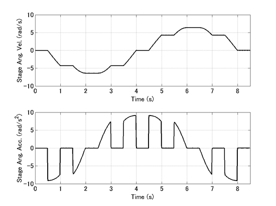
From the simulation result, the angular velocity and the angular acceleration of the stage are plotted in Figure 4. It can be seen that when the arm angle changes (refer to Figure 3), the rotation of the stage is accelerated due to the gyro moment. When the arm angle is closer to ±90 degrees, the stage is accelerated less. This is because the gyro moment vector tilts closer to horizontal and its vertical component reduces.